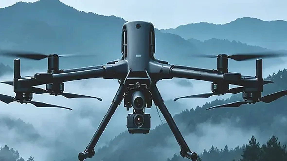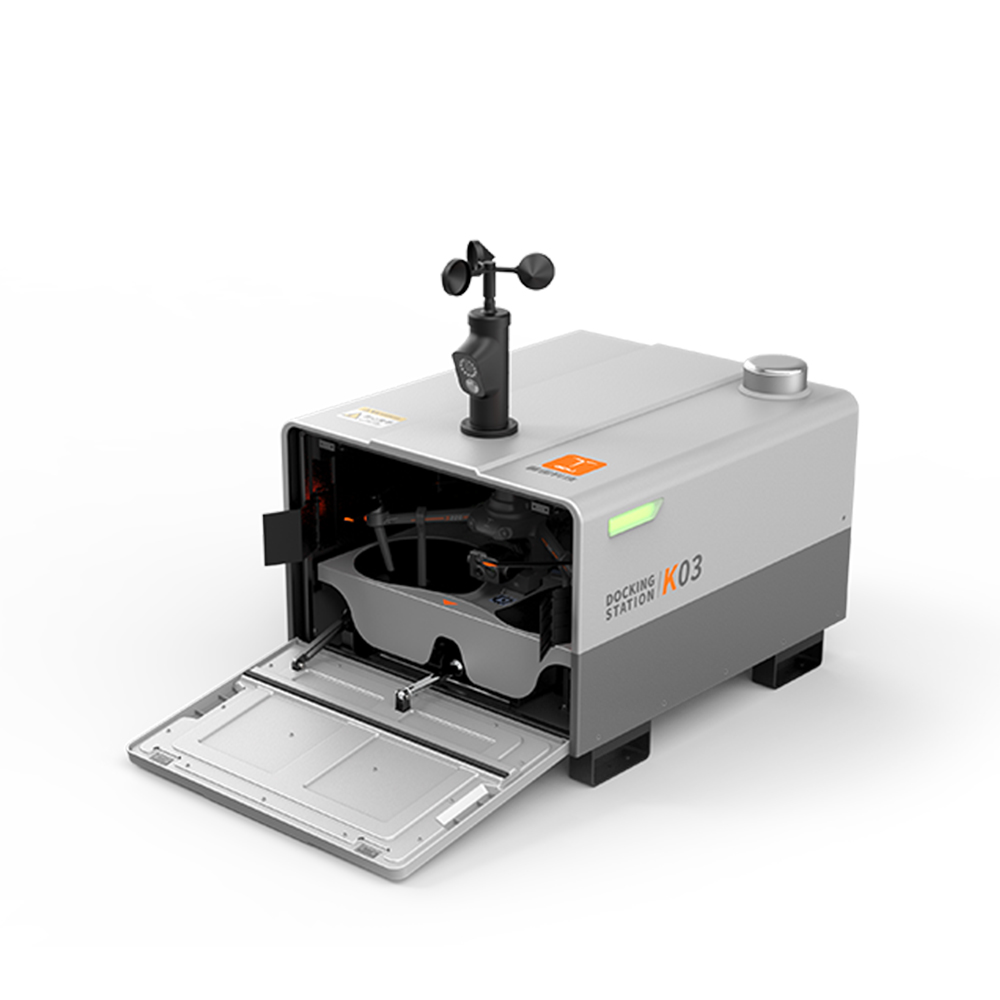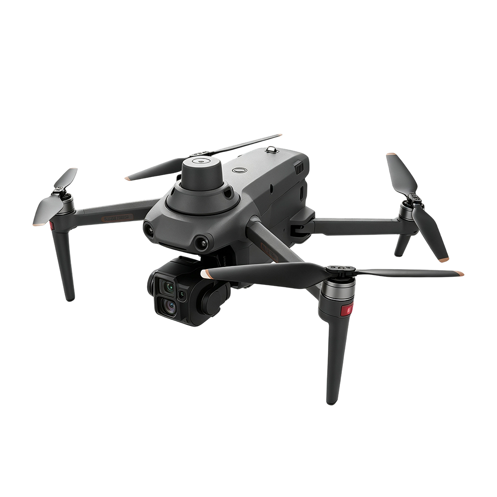
Micro Gimbal Integration in Practice: How to Split Your SWaP Budget So Small Aircraft Can Carry It, See Clearly, and Stay Airborne
The question asked most often during payload selection is "how many grams is this gimbal." But what actually determines whether a configuration works is not the number on the datasheet. It is how much payload margin the aircraft has left, and how many devices that margin has to be split between. What blocks a platform is rarely the lightness of the gimbal itself, it is the gap between the available payload budget and the real installed weight.
The S220 PRO weighs 1,860 g empty with a maximum takeoff weight of 2,050 g, leaving only 190 g of total margin to allocate. EO/IR gimbals commonly used in the industry sit in the 2 kg class, which exceeds that limit outright and means the aircraft cannot take off at all. The FY-VT04 vertical takeoff and landing fixed-wing offers an even clearer comparison: 240 minutes of endurance empty, 220 minutes with 0.5 kg aboard, and 140 minutes at 1.5 kg, so that extra kilogram costs 80 minutes of flight time.
This article sets out the full integration logic for micro gimbals: how to account for SWaP (size, weight, and power), why datasheet weight differs from installed weight, how much power margin to reserve, why thermal management fails most often, how to handle interfaces and boresight alignment, and the five pitfalls most likely to surface during deployment.
Updated September 2026. Compiled from publicly available sources and measured integration data.
Key figures first (market size plus real platform specifications, to help you decide whether to keep reading):
- The global drone payload market is valued at roughly US$13.6 billion in 2026 and is projected to reach US$32.4 billion by 2033 (CAGR 13.2%, Persistence Market Research, February 2026 report)
- EO/IR is the single largest payload category, accounting for around one quarter; platforms carrying under 25 kg make up the bulk of deployments (same report)
- The S220 PRO has a total payload budget of just 190 g (1,860 g empty / 2,050 g maximum takeoff), so a conventional 2 kg gimbal cannot be carried
- FY-VT04 endurance curve: 240 minutes empty / 220 minutes at 0.5 kg / 140 minutes at 1.5 kg, meaning one extra kilogram costs 80 minutes
- Payload versus empty gap on the 10-inch FPV: 2.5 to 3.0 kg maximum payload, 30 minutes empty, only 8 to 12 minutes fully loaded
- CGTD095 micro dual-sensor gimbal: head 104 g ±5 g, steady-state power ≤10 W, stabilization accuracy ≤0.02°, head dimensions 58×57×79 mm, control box 59×55×24 mm
- Stabilization accuracy converts directly into "can you actually see it": one milliradian is roughly one meter of offset at one kilometer, so ≤0.02° works out to about 0.35 m of displacement at 1 km
What a micro gimbal does: five core tasks
1. Night search and rescue on small aircraft (finding people with thermal)
Finding people at night is the strongest case for micro gimbals. Human eyes and visible-light cameras are largely ineffective after dark, while thermal imaging reads temperature rather than light, so a human heat signature appears as a bright spot. The difficulty is that gimbals able to carry a thermal sensor are usually not small, while aircraft able to work through trees or narrow alleys cannot lift them. The role of a micro gimbal is to move thermal capability down from large platforms onto aircraft in the few-kilogram class. The operating logic described in desert search and rescue drones depends fundamentally on that downward shift.
2. Long-endurance inspection (trading weight for flight time)
For pipeline patrols, forest and grassland monitoring, and coastline surveys, what the customer is buying is not primarily resolution but area covered per sortie. Following the measured FY-VT04 curve, moving from a 1.5 kg payload down to the 0.1 kg class does not save a few minutes, it returns flight time measured in tens of minutes. For inspection projects billed per square kilometer, that difference directly determines daily output per aircraft.
3. Multiple payloads coexisting (a lighter gimbal leaves room for a second device)
Many projects do not carry only one item. The gimbal observes, the loudspeaker broadcasts, and sometimes a drop device or a data relay has to come along too. The payload budget is fixed, so if the gimbal consumes half of it the remaining two devices become an either-or choice. Holding the gimbal to the 100 g class hands the remaining margin to the equipment that performs the actual task. The multi-payload combinations discussed in remote-area drone delivery run into exactly this constraint.
4. Target geolocation (converting stabilization accuracy into "can you see it clearly")
Detecting a target is only the first step, delivering accurate coordinates is the actual deliverable. Translating ≤0.02° into distance makes this concrete: about 0.35 m of line-of-sight displacement at 1 km and roughly 0.7 m at 2 km. At that level the image does not blur from airframe vibration and the target holds a stable position in frame, which is what makes subsequent ranging and coordinate calculation meaningful. What thermal plus zoom dual-sensor configurations describe is precisely how to push from detection through to geolocation.
5. Operating in high and low temperature environments
For customers in the Middle East and Africa the dominant problem is not cold but heat. Ground temperatures above 50°C at midday combined with a gimbal mounted inside a sealed bay without airflow will drive the unit into protection. Micro gimbals draw less power and therefore generate less heat in the first place, which is a natural advantage in hot climates. The CGTD095 is rated for operation from -20°C to +55°C, with storage from -45°C to +60°C.
The weight account: datasheet figures are not installed weight
First, work out how much budget the aircraft has left
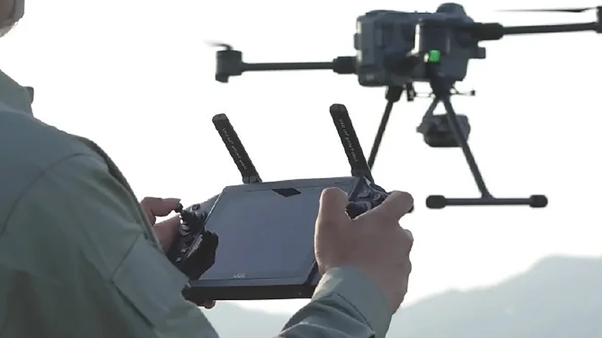
The first step before integration is not choosing a gimbal but calculating the platform payload budget. The table below lists real specifications from four platforms, and the differences between them are larger than most people expect.
| Platform | Payload limit | Endurance | What it means |
|---|---|---|---|
| S220 PRO | 2,050 g maximum takeoff, 1,860 g empty, about 190 g of margin | 41 minutes maximum flight time | Budget is extremely tight, the gimbal has to reach the 100 g class, anything above that exceeds limits |
| FY-VT04 VTOL fixed-wing | 2.0 kg maximum payload (11.8 kg empty) | 240 minutes empty / 220 minutes at 0.5 kg / 140 minutes at 1.5 kg | Budget is comfortable, but marginal cost rises the closer you get to the limit |
| 10-inch FPV | 2.5 to 3.0 kg maximum payload | 30 minutes empty / 8 to 12 minutes fully loaded | Carrying 100 g versus carrying 2 kg yields two completely different working capabilities |
| TS100 transport drone | 100 kg maximum payload | 50 minutes empty / 10 minutes at 100 kg | Budget is ample, differences at the 100 g level are negligible, miniaturization is not its pain point |
The last row needs a specific note. Not every platform needs a micro gimbal. A 100 kg-class transport platform such as the TS100 is not short of 100 g, and fitting a micro gimbal there sacrifices sensor specification instead. The value of miniaturization concentrates in platforms with tight margins such as the S220 PRO, small and medium FPV platforms, and light VTOL fixed-wings. The logic behind payload allocation on long-endurance VTOL platforms is covered in the FY-VT04 long-endurance VTOL guide.
Next, see how much the gimbal itself consumes
The second place errors appear is here. The weight printed on a gimbal datasheet is usually only the head assembly and excludes the control box, cabling, vibration isolators, and interface box. The table below compares real figures across the micro gimbal range, with datasheet head weight on the left, total installed weight on the right, and the difference in between being the part you only discover after installation.
| Model | Head weight | Total weight | Difference | Dimensions |
|---|---|---|---|---|
| CGTD055 | 55 g ±5 g | ≤90 g | about 35 g | 46×44×52 mm |
| CGTD070A | 80 g ±5 g | ≤105 g | about 25 g | 57×50×62 mm |
| CGTD070B | 90 g ±5 g | ≤128 g | about 38 g | 60×50×62 mm |
| CGTD090 | 80 g ±5 g | ≤122 g | about 42 g | 57×50×62 mm |
| CGTD095 | 104 g ±5 g (servo 42 g ±2 g) | [to be confirmed] | per measured total | head 58×57×79 mm, control box 59×55×24 mm |
| CGTT155 | 165 g ±5 g | 207 g | 42 g | 79×75×90 mm |
Taking the CGTD070B as an example, the head is 90 g and the total is 128 g, so the additional 38 g accounts for more than 40 percent. If the platform budget is only 190 g, that difference is enough to turn a viable configuration into one that cannot be flown. Always calculate against weighed installed weight before integration, never against the datasheet figure.
Power and thermal management: the gate most easily overlooked
Steady-state draw is not total draw
The CGTD095 is rated at ≤10 W steady state with a supply range of DC 10.8 to 26.4 V at 3 A. The common miscalculation is treating the steady-state value as the total. At startup, during rapid motor repositioning, and in cold conditions, current rises well above steady state. If the power supply is designed with only steady-state margin, voltage sag in flight will cause repeated gimbal restarts. Peak inrush current is marked [to be confirmed] and should be requested from the supplier as a measured value during selection.
Heat inside a sealed bay triggers throttling
Thermal behavior is the other frequent failure point. Electronics mounted in a sealed bay, running at high duty cycle in a hot environment, will climb toward the protection threshold and then actively reduce output, showing up as frame stutter, lost tracking, or in severe cases outright restarts. Customers in the Middle East and Africa hit this noticeably more often in summer. Countermeasures include leaving a convection path around the gimbal, mounting the control box away from other heat sources, and completing a long ground run-in before delivery so the temperature curve is known before the aircraft flies.
Interfaces and stabilization: it has to stay usable once fitted
Choosing between three control interfaces
The CGTD095 offers TTL serial, network, and SBUS control interfaces, and the choice depends on flight controller and link architecture. TTL serial is the simplest and suits direct command output from the flight controller. The network interface suits scenarios needing simultaneous streaming and control, with better bandwidth and expandability. SBUS can run directly through a receiver channel without consuming flight controller resources. Interface protocol must be confirmed with the flight controller team before purchase, since discovering a mismatch during integration costs far more to fix than choosing the wrong model.
Converting stabilization accuracy into "can you see it clearly"
A standalone ≤0.02° figure lacks context, so converting it to distance makes it judgeable. One milliradian is roughly one meter of offset at one kilometer, and 0.02° converts to 0.349 milliradians, meaning about 0.35 m of line-of-sight displacement at 1 km and roughly 0.7 m at 2 km. At that level the target holds a stable position in frame rather than drifting with airframe vibration. If accuracy is an order of magnitude worse, the image at the long focal length end will shake continuously and both AI tracking and coordinate calculation lose accuracy. The locking logic behind AI tracking gimbals presupposes a stable image in the first place.
Review: five pitfalls that most often derail integration
Pitfall 1: counting the gimbal but not the control box and cabling
A configuration review calculated on head weight, then integration adds the control box, cabling, isolators, and interface box, pushing real weight 30 to 40 percent over budget and leaving takeoff weight excessive or the center of gravity too far aft.
Solution: build the parts list against total installed weight and weigh every item; reserve more than 30 percent margin on tightly budgeted platforms.
Pitfall 2: treating steady-state draw as total draw
Power designed only for steady state lets startup peaks pull the voltage down, causing repeated gimbal restarts and intermittent video.
Solution: request measured peak inrush current from the supplier, design supply lines to peak plus margin, and allow extra compensation for voltage drop on long cable runs.
Pitfall 3: isolators too soft or too hard
Isolators that are too soft amplify low-frequency sway and the whole image rocks. Too hard and high-frequency vibration passes straight into the optics, leaving the image jittery and detail lost.
Solution: keep isolation frequency away from the airframe's dominant vibration band, record a hover video after integration, inspect frame by frame for rhythmic shake, and change durometer and retest if needed.
Pitfall 4: heat in a sealed bay triggers protective throttling
A gimbal installed in a sealed bay with no airflow triggers thermal protection after ten or so minutes of summer operation, freezing or restarting the video.
Solution: leave intake and exhaust openings in the bay to create convection, keep the control box away from other heat sources, and complete a long ground run-in before delivery with the temperature curve recorded.
Pitfall 5: boresight drift without recalibration
The boresight is aligned once at integration, then temperature cycling and vibration shift it gradually, so systematic error in ranging and geolocation accumulates while remaining invisible to the operator on screen.
Solution: write boresight recalibration into the maintenance schedule, calibrate before and after each relocation on long projects, and in regions with large temperature swings let the bay stabilize thermally before aligning. Systematic effects from center-of-gravity shift should also be accounted for, with CG position recalculated after installation.
In one sentence
The value of a micro gimbal is not lightness for its own sake, it is handing the saved grams and watts to the job that actually matters: either buying back tens of minutes of endurance, freeing margin for a second device, or moving a capability that once required a large aircraft down onto a smaller, cheaper, and less conspicuous platform. The order of calculation is confirm remaining platform payload first, then account for total installed gimbal weight, and finally fold in the control box, cabling, and thermal load.
We need your scenario
Whether you are integrating, running industry projects, or building your own aircraft, send us a description of your scenario and we will calculate the SWaP budget and recommend a configuration at no cost.
- FPV and small aircraft integrators (need multiple sensors on a small platform) → we reverse-derive payload allocation from your takeoff weight and endurance target
- Industry integrators (inspection, search and rescue, security projects) → we provide a platform, gimbal, and interface installation list including power and thermal recommendations
- Aircraft manufacturers (own-platform integration, such as VTOL fixed-wing or heavy-lift models) → we support interface bring-up and installation verification, with the support path described in our distributor and project support program
To respond: leave a message on the inquiry page marked "micro gimbal SWaP budget" and the technical team will reply within 24 hours. Selection advice is free of charge.
FAQ: Frequently Asked Questions
How much flight time does the weight saved by a micro gimbal actually buy back?
It depends on the platform and there is no universal formula. The measured curve offers a reference: the FY-VT04 VTOL flies 220 minutes at 0.5 kg and drops to 140 minutes at 1.5 kg, so that one kilogram corresponds to 80 minutes, and the marginal cost is progressive, getting more expensive the closer you approach the payload limit. The contrast is sharper on small platforms, where a 10-inch FPV flies 30 minutes empty but only 8 to 12 minutes fully loaded at 2.5 to 3.0 kg. Specific figures need to be calculated against the payload-endurance curve for that airframe, which can be requested during selection.
How much does datasheet weight usually differ from installed weight?
It depends on model and construction. Across the micro gimbal range the measured difference runs from 25 to 42 g, representing 30 to 40 percent of head weight, mostly from the control box, cabling, isolators, and interface box. Platforms with tight budgets, such as the S220 PRO with only 190 g of total margin, must be calculated against installed weight. Ask suppliers for weighed total figures before integration rather than head weight alone.
What goes wrong if power is designed only for steady-state draw?
The typical result is that current rises well above steady state at startup and during cold starts, pulling supply voltage down, restarting the gimbal repeatedly, and breaking up the video. The CGTD095 is rated ≤10 W steady state with DC 10.8 to 26.4 V at 3 A, but peak inrush is a parameter that needs separate confirmation. Request measured peak values when designing the supply, and allow extra voltage drop compensation on long cable runs.
What level of performance is ≤0.02° stabilization accuracy?
Converting to distance makes it judgeable. One milliradian is roughly one meter of offset at one kilometer, and 0.02° converts to about 0.349 milliradians, meaning roughly 0.35 m of line-of-sight displacement at 1 km and about 0.7 m at 2 km. At that level the target holds position in frame, so ranging, coordinate calculation, and AI tracking all remain meaningful. If accuracy is an order of magnitude worse, the image at the long focal length end shakes continuously and both tracking and calculation lose accuracy.
Does a micro gimbal overheat more easily in high temperatures?
Low power consumption actually gives it an advantage in heat, since it generates less of it and puts less strain on cooling than high-power gimbals. The CGTD095 is rated -20°C to +55°C operating and -45°C to +60°C storage. The real risk comes from installation rather than the gimbal itself, since a sealed bay without airflow or a control box pressed against other heat sources will trigger protective throttling. A ground run-in before installation is recommended for Middle East and Africa customers.
Which platforms suit micro gimbals and which do not need them?
The greatest value is on platforms with tight margins: the S220 PRO at roughly 190 g total, small and medium FPV platforms (7-inch payload 1.5 to 2 kg, 10-inch 2.5 to 3.0 kg, 13-inch 5 to 6 kg, 15-inch 7.5 kg), and light VTOL fixed-wings. The reverse also holds, since a transport platform like the TS100 with 100 kg maximum payload is not short of 100 g, so fitting a micro gimbal there sacrifices sensor specification and a higher-specification model would serve better. The first step in selection is deciding which category your platform falls into.
How do you choose between TTL serial, network, and SBUS interfaces?
The deciding factor is flight controller and link architecture. TTL serial is simplest and suits direct command output from the flight controller. The network interface suits scenarios needing simultaneous streaming and control, offering better bandwidth and expandability. SBUS can run directly through a receiver channel without consuming flight controller resources. What matters is confirming the protocol with the flight controller team before purchase, since discovering a mismatch at the integration stage costs far more than choosing the wrong model.
Disclaimer: this article is compiled from publicly available sources and measured integration data. Specifications should be confirmed against the supplier's latest datasheet and measured values.